Bo Nordell
Division of Water Resources Engineering
Luleå University of Technology
S-97187 Luleå, Sweden
phone: +46-920-91646
fax: +46-920-91697
1 BACKGROUND
The methods most commonly used to determine the ice cover thickness (Fransson, 1991) are:
Measurement stick: The ice thickness is measured in a borehole through the ice, by a measurement stick. Sometimes a thin steel wire is permanently placed in the hole. This wire is heated to open the hole each time measurements are performed.
Temperature measurements: A number of temperature gauges are evenly spaced along a wire from the ice surface to the depth of the expected maximum ice thickness. The temperatures are measured and recorded and the interface between the ice and water is defined by the freezing temperature (0 C) of water. So, this method indicates if the temperature gauges are within or below the ice cover. The method results in discrete values of the ice thickness because a certain number of temperature gauges and a corresponding number of ice cover thicknesses are investigated. Analysis of the densely measured temperatures makes it possible to interpolate between the gauges to obtain a "semi-continuous" ice cover thickness.
Float: A float is located in a borehole through the ice, that is filled with kerosene to keep it open. The ice thickness is determined from the distance measured between the ice surface and the kerosene surface. This method gives erroneous results if snow covers the ice. The reason is that the snow load presses the ice cover down into the water, which decreases the measured value. Radar Measurements (Yankielun, 1992): Radar measurement of ice thickness is a fast method because the measurement equipment can be carried by e.g. snow-mobiles or helicopters. This method gives continuous values in space but discrete values in time.
None of these methods are continuous in space and time and all, except the airborne, also require a certain ice thickness, strong enough to carry the load of the equipment. In many applications a method that works for any ice thickness and gives the ice thickness as a function of time would be desired.
In a recent study by Nordell and Westerström (1995 ) a new principle for continuous measurement of ice cover thickness was presented. The measuring device consisted of a water-filled bucket, floating with its brim at the water surface. A pipe was vertically mounted at the centre of the bucket, ending in an oil-filled balloon. The volume expansion of the formed ice results in a corresponding oil flow, from the balloon at the bottom of the bucket through the pipe into an expansion bucket above ground. By measuring the volume expansion continuously, the ice thickness is determined at any time. The performance of preliminary laboratory tests confirmed the feasibility of the method.
In this study, financed by Coldtech, Miljöbygg AB and Idé Arktica, a prototype of the ice thickness meter was developed. The theoretical work has been performed by the Division of Water Resources Engineering at Luleå University of Technology. The field tests have been carried out by Idé Arktica in Övertorneå.
2 NEW MEASUREMENT METHOD
2.1 General
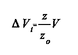
A bucket of volume V (m3) with the active height zo (m), filled up with water, floats with its upper brim at the water surface. The bucket is open to the air according to Figure 1. A pipe is vertically mounted at the centre of the bucket, ending in a balloon. The pipe and the balloon are filled up with oil. In the surrounding cold air the water freezes from the top, and the unfrozen water is confined by the formed ice layer and the walls of the bucket. As a result of the volume expansion of the formed ice, the corresponding volume of oil flows through the pipe to an expansion bucket. The volume of the oil accumulated in the expansion bucket is continuously measured and recorded, and the ice cover thickness can be calculated.
2.2 Theory
When the ice thickness is z (m) from the surface, Figure 1, the volume of ice Vi (m3) of the total volume V (m3) is:
Conservation of mass gives the volume of the frozen water Vw (m3) before freezing:
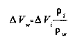
where the densities of ice and water at 0 C are denoted by i and w respectively. By inserting the density values of ice and water at 0 C, 917.3 kg/m3 and 999.84 kg/m3 respectively, into eq.(2) it is seen that Vi> Vw (Hobbs, 1974).
In a confined bucket this would result in a pressure increase. However, the pipe (Figure 1) drains the volume expansion by conducting the corresponding volume of oil from the balloon to the expansion bucket. So the only pressure that occurs in the bucket is the oil pressure from the expansion bucket. If the distance between the expansion bucket and the ice surface is small, this pressure will not influence the test. A pressure corresponding to 1 m of water reduces the freezing point of water by 0.000737 C (Nordell, 1990).
The volume difference between the ice and unfrozen water gives the volume expansion, i.e. the volume of the oil in the expansion bucket, (m3):
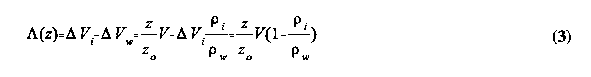
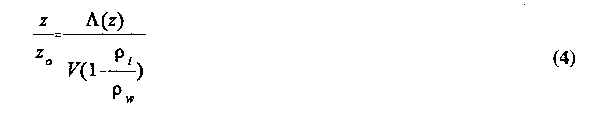
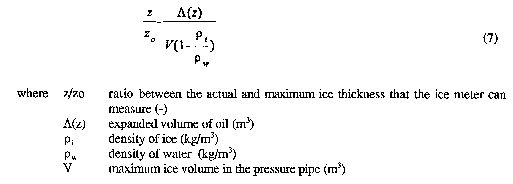
So, the ice thickness as a function of the expanded volume is:
If the volume expansion is measured as the mass m (kg) of the expanded oil volume of density o (kg/m3) then:
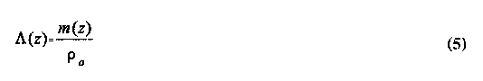
After inserting eq.(5) into eq.(4) the ice thickness z is obtained as a function of the expanded mass of oil:
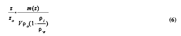
The analysis results in a simple linear expression. The properties of ice, water and oil are well defined and constant, at the occurring freezing temperature (0 C) and normal pressure.
2.3 Preliminary Test
A preliminary laboratory test was performed, to see if this idea would encounter any unforseen problems. In this test the floating device was not examined. To simulate the one-dimensional heat flow from the water through the ice cover, the water-filled bucket was thermally insulated at the bottom and its vertical sides.
A heat-insulated glass bucket, 1000 ml, was filled up with water. A glass pipe was placed vertically in the centre of the bucket and a thin rubber balloon was mounted at the end of the pipe. The pipe and the balloon were filled up with oil to the bottom of the expansion bucket. The equipment was placed inside a freezer. As a result of the heat insulation around the sides of the water-filled bucket, ice formed from the top.
The volume of the oil that accumulated in the expansion bucket was recorded manually. At the
same time the ice thickness was measured. The ice front was located and measured by temporarily removing the heat insulation. The water was coloured to simplify the location of the ice front. Figure 2 shows that the measurements were in agreement with eq.(4), i.e. there is a linear relation between the volume expansion and the ice cover thickness.
2.4 Discussion and Conclusions
This method of continuous measurement of ice cover thickness was tested in a preliminary laboratory test. Though manual measurements were made, see Figure 2, the basic idea of continuous measurement was shown. An electronic weighing machine, connected to a recording system, could have been used for continuous measurements of the expanded mass.
There are some basic problems to consider. Should the expanded volume be measured as mass or volume? Should the measuring unit be placed on top of the bucket or should it be located some distance away? The measurement method should work from the initial freezing to the formation of the maximum ice thickness. Should the method also work in thawing situations, i.e. when the ice cover thickness is reduced? In such situations the evacuated volume expansion must be refilled.
3 PROTOTYPE DESIGN
3.1 General
The ice thickness is proportional to the volume expansion of the ice formed. In the suggested measurement device this volume expansion results in a corresponding oil flow from the measure-ment pipe to an expansion bucket. So, the ice cover thickness is measured by determining this volume of oil. In its simplest form of the measurement device the volume of oil in the expansion bucket (measure glass) is directly read as the thickness of the ice cover.
The volume of oil, i.e. the depth of the oil in the expansion bucket, could also be measured with a potentiometer. This means that a resulting voltage, proportional to the oil volume, is obtained from the potentiometer. Such electric signals could easily be stored into some type of processor.
It is also possible to determine the volume of oil by optical, sound and other types of devices.
Another way to determine the expanded oil volume is to measure its mass. This could easily be made with some type of electronic weighing machine.
It is also possible to measure the pressure of the oil volume at the bottom of the expansion bucket and from this pressure the volume (mass) of oil is derived. This method was chosen for the proto-type ice thickness meter because:
1/ Suitable pressure gauges were already devolved and easily available for the purpose of determining small volumes of liquid.
2/ The selected pressure gauge eliminates the influence of the atmospheric pressure changes since by measuring the difference between the total pressure and the atmospheric pressure.
3/ The piezoelectric pressure gauge is well protected against moist, wind, snow and rain.
4/ The pressure gauge is relatively cheap
Since the physics and the principle of the measurement device was solid the development of the prototype started by listing the requirements of the prototype. The corresponding list of require-ments for a future and more advanced ice thickness meter is found in Section 5.
3.2 Requirements for Prototype
The project group discussed different factors that should be consider before the prototype ice thickness meter (ITM) was constructed. Some of these were:
Snow cover: The ITM must not influence the ice cover thickness, e.g. directly by influencing the heat transport or indirectly by influencing the snow cover, at the location of the measurement.
Wind/Water Flow: The ITM must work in streaming water and strong winds, which must be con-sidered in the design of the float and the anchor.
Indication: There must be some sort of mark (e.g. flag) to indicate the location of the ITM to avoid that snow mobiles runs over the gauge.
Construction: The construction must be strong and the ITM should be possible to transport and install by one person i.e. the ITM must of low weight. The height of the ITM is mainly a result of the maximum expected ice thickness.
Materials: The materials and components of the ITM must be resistant to the climate i.e. water, ice, snow, wind, moist and low temperatures. The thermal properties, especially the thermal con-ductivity, of the measurement pipe should be close to that of ice and water to avoid unseasonable melting, close to the measurement pipe, because of solar radiation on the ITM.
Based on the above mentioned different factors take under consideration the requirements of the prototype ice thickness meter were defined:
Must work in streaming water
Protected against climate (wind, moist, snow and rain etc.)
Electrically powered by battery or connected to the net
Expanded oil volume determined by pressure measurements
Data measurements and recordings at optional frequency
Storage capacity of the processor sufficient for the one winter of measured data
Measured Data
- time
- oil volume (pressure)
- 8 more channels to record climatic data (temperature, wind speed etc)
PC connection to tap measured data
3.3 Prototype Design
3.3.1 Float
To make the prototype work in streaming water a lot of floats were constructed and tested. The field tests were performed on the Torne River during the winter 1994/95 by Idé Arktica in Över-torneå. The tested floats were of different materials and forms i.e. circular, triangular and of irregular shape. To achieve one of the requirements, that the prototype must be applicable in streaming water, the irregular form proved, see Figure 3, to be most successful. The float was made of styrofoam covered with plywood on top of the float.
In an existing ice cover the ice thickness meter would be easily placed in a hole in the ice but to measure the first ice of the season the ice thickness meter must be placed in the water before the ice is formed. Consequently, an anchor has to be used to keep the ice thickness meter in position. The anchor itself was easily solved but the varying water depth meant varying weight of the anchor wire. Because of the streaming water the anchor wire does not go vertically to the bottom. The drag force on the float and the wire thus varies and the resulting angle between the float and the anchor wire varies with both the depth and flow velocity. To keep the float horizontally on the water surface the location of the datalogger box on top of the float was made adjustable, see Figure 4
3.3.2 Measurement Pipe
The measurement pipe must not increase or decrease the forming of ice close to the ice thickness meter. Consequently, the thermal properties or more specifically the thermal conductivity of the measurement pipe material should be close to that of water/ice. The thermal conductivities of steel, plastic and ice are about 200, 0.6 and 2 W/m,K respectively. So if a steel-pipe was used the ice thickness would become greater at the ice thickness meter since heat is more easily transported through the pipe than through the ice. This would cause problems also during sunny days when the solar radiation would melt the ice inside and out side the ice thickness meter. The diameter the measurement pipe should not be to wide to reduce the drag force of the streaming water.
The thermal conductivity of plastic is relatively close to that of ice and there are also other advan-tages e.g. it is an inexpensive material with a low weight, which reduces the size of the float. Consequently, the measurement pipe was constructed of plastic (PVC) with an outer diameter of about 50 mm and a wall thickness of 3 mm.
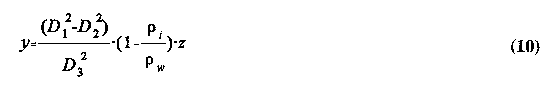
The expanded volume of oil from which the ice thickness is calculated is derived from eq.(7) previously given as eq.(4) and eq. (8).
The diameter of the expansion bucket is D3 and the level of oil is y (m).
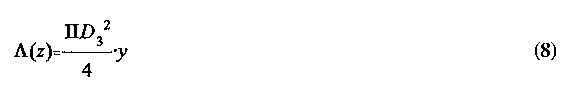
Since (z) in eq.(7) and eq.(8) express the expanded oil volume we have:
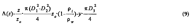 where D1 (m) is the inner diameter of the measurement pipe and the D2 (m) the
outer diameter of
where D1 (m) is the inner diameter of the measurement pipe and the D2 (m) the
outer diameter of
the connecting pipe and y (m) is the oil level in the expansion bucket. By cleaning the expression and solving y, eq.(10) is obtained.
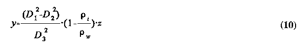
In this case, see sections 3.3.2 - 3.3.3, when we know that D1=44.75 mm; D2=10.15 mm and D3=20.75 mm and that the densities of water and ice are 917.4 kg/m3 and 999.84 kg /m3 respectively, the oil level in the expansion bucket as a function of ice thickness becomes:
3.3.3 Expansion System and Oil
The expansion bucket or the measurement glass is made of plexiglass through which the level of the evacuated oil can be seen. The inner diameter of the expansion bucket is 20.75 mm. The oil pipe that connects the balloon to expansion bucket is a 10.15 mm PEX pipe.
Several oils have been tested and the main problem was that most oils dissolve rubber. The oil finally chosen was a Silicon oil with a viscosity of 20 cs (centistokes), which is commonly used in different applications e.g. lubrication of rubber. The viscosity of 20 cs means that the viscosity is very low i.e. the oil is extremely fluent. Since it is used to lubricate rubber it should also able to use in contact with rubber (the balloon).
The thermal volume expansion of the different oils were measured by Idé Arktica and the thermal volume expansion coefficients were about 10-3 K-1. The thermal volume expansion coefficient of the Silicon oil used, type 47V20, was given to 1.07 10-3 K-1 by the supplier company, SIKEMA AB in Stockholm. This expansion must be considered in the future measurement systems.
3.3.4 Balloon
The oil-filled balloon at the bottom of the measurement pipe is used to evacuate the volume expan-sion of water when ice is formed. This balloon must be made of a thin material that is resistant to the oil used.
Several easily available rubber balloons were tested but they all failed to hold the oil. (During these tests Silicon oil was not used). The rubber was dissolved after a leakage occurred after hours or days. Finally, we found that rubber of latex was resistant to oil.
Such balloons of our size and shape were not available. Specially made latex balloons are manufactured by PDC AB in Ängelholm, the only Swedish special balloon company. This com-pany delivers any type of balloon (size, shape and material) and will produce balloons for the ice thickness meter. Unfortunately the latex rubber was very expensive and we had to buy a minimum 200 kg á 150 SEK. PDC also made the matrix which was used to form our balloon. Balloons of latex rubber were not used in this project but should be used in future measurement equipments. In our short-term tests cheaper rubber balloons were used.
3.3.5 The Datalogger System
The electronic equipment, the power supply, processor and computer programs necessary to operate the ice thickness meter automatically were delivered by anima elektronik AB, Piteå.
The datalogger has 10 channels available to collect data according to Table 1. The datalogger is guaranteed for an ambient temperature of -40oC.
3.3.6 Pressure Gauge
The chosen pressure gauge is a PROTRAN Differential Pressure Transmitter, Type PR3202 Ultra Low Range. The pressure is measured by a piezoelectric system as the differential pressure between the atmospheric pressure and the pressure at the bottom of the expansion bucket. This latter pressure is the sum of the pressure of the oil volume in the bucket and the atmospheric pressure, since the bucket is open to the air. The differential pressure measurement thus gives the resulting pressure of the oil volume only. The pressure range is 100 mbar, supply voltage is 13-30 Vdc and the output signal is in the range 4-20 mA with a linearity of +/- 0.125 %.
4 TESTS
4.1 Field Tests
The performed field tests were extremely time consuming for the very few measured values obtained. This is because of the nature of this type of measurements, the very slow growth of the ice cover thickness. The ice cover thickness meaurements were verified by drillings and measure-ment of the ice thickness through the hole in the ice. The measurements were performed during November at the end of 1994. At this time the datalogger was not yet in operation, so, the measurements were made manually by reading the level of oil in the expansion bucket.
In this field test the walls of the expansion bucket was slightly thicker than in the present, 19.8 mm compared to 20.75 mm, which meant that the oil level was expected to raise 0.4 mm per mm of ice cover, see eq.(11). It is seen in Table 2 that the oil level exactly gives the expected response until the oil level of 23 mm is reached (*). A vegetable oil, Hydrap Oil, was used in this test.
The ITM was lifted off the water and the problem was investigated. It was found that there were air bubbles in the oil. These air bubbles would explain the occurring problems. Other problems were observed at this occasion. Ice was forming along the metallic rack that held the measurement pipe of the ITM i.e. the instrument influenced the ice cover thickness. At this time it had not yet reached the measurement pipe but the ITM was reconstructed. Now the material of the rack that held the measurement pipe in position was exchanged from metal to plastics (PVC). The material of the holders of the measurement pipe was exchanged for PVC.
This teset resulted also in a change of oil, the Hydrap Oil was changed to ATF Oil for two reasons: 1/ The viscosity of the ATF Oil is not changing with temperature as much as the Hydrap Oil did. 2/ The ATF Oil is red, which simplifies the reading of the oil level.
It was decided to continue the field tests as soon as the data logger was delivered. The logger was, however, not delivered and tested during the time the ice was safe, so, this was the only field test performed.
4.2 Continued Laboratory Tests
A new laboratory test equipment was constructed at the workshop of Idé Arktica. In this equipent the ITM is built-in in a freezer. The measurement pipe in the freezer is about 1.5 m and the datalogger and the expansion bucket is mounted on top of the freezer. Several tests were made and these measurements resulted in reconstructions of the datalogger and the program used to tap data. Examples of measured data are shown in Appendix 1.
.
Figure 6. Two sections and a plan drawing of the ice thickness meter.
5 CONTINUED WORK
With this prototype equipment we have solved many of the problems we have met (0) but there are still work to do (X):0 Must work in streaming water
0 Protected against climate (wind, moist, snow and rain etc.)
X Electrically powered by battery recharged by solar panel
0 Expanded oil volume determined by pressure measurements
0 Data measurements and recordings at optional frequency
X Frequency of data measurements and recordings controlled by measured data
X Positioning of the ice thickness meter by GPS (Ground Positioning System)
X Communication via wireless telephone
X Storage capacity of the processor sufficient for the one winter of measured data
0 Measured Data
0 - time
0 - oil volume (pressure)
0 - more channels to record climatic data (temperature, wind speed etc)
0 PC connection to tap measured data
X Tap measured data via wireless telephone
The work to develop the ice thickness meter will continue at the Division of Water Resources Engineering at Luleå University of Technology and Idé Arktica in Övertorneå. We still have some problems to solve concerning the datalogger (processor). This will probably be solved within an other project, to develop the same principle or idea to a frost depth measurement device. In this project we will use the same datalogger system.
Further studies have to be performed on the theoretical details of the ITM. Functions for how to consider the e.g. the thermal expansion of the oil and the materials of the ITM has to be derived. These functions should be included in the processor of the ITM. This work should preferably be performed by a doctorand to a degree of at least licentiate. Even if laboratory tests are i many ways efficient, field tests must also be carried out during several winters to test the equipment during the conditions the ITM is supposed to endure.
A small company in Övertorneå, KABLIA AB, will most probably manufacture both measurement equipments. This company, which is about ten years old and has 10 employees, manufactures cables and connections for computers and other and electronic equipment. They are, however, expanding their business and within their group they have necessary competence to be successful with this measurement equipment.
Acknowledgements
We acknowledge Coldtech, Miljöbygg AB and Idé Arktica for their financial support of this study.
6 REFERENCES
Fransson, L. (1991). Methods to measure ice cover thickness (Metoder att mäta istjocklek).
Coldtech 91:2, Department of Structural Engineering, Luleå University of Technology, Sweden. (in Swedish)
Hobbs P.V. (1974). Ice Physics. Clarendon Press, Oxford. U.K.
Nordell, B. (1990). Measurements of P-T coexistence curve for ice-water mixture. Cold. Reg. Sci. Technol. 19:83-88.
Nordell, B and Westerström, G. (1995). Method for Continuous Measurement of Ice Cover Thickness. Cold Reg. Sci. Technol., Vol.23, No. 4. (Sep. 1995).
Yankielun N.E. (1992). An Airborne Millimeter-Wave FM-CW Radar from Thickness Profiling of Freshwater Ice. Cold Regions Research and Engineering Laboratory CRREL Report 92-20, New Hampshire, U.S.A.
Datalogger laboratory tests Appendix 1 Page 1/3
The test of the datalogger started 950420. Several unintentional stops occurred. Before start at 13.50 methylene blue was added to make it easier to located the ice line (ice depth) in the measurement pipe. To achieve freezing from the top of the pipe the pipe was thermally insulated with circular styrofoam plates with a thickness of 50 mm. A number of these circular plates were stacked on each other along the pipe. As ice formed t'he height of the thermal insulation was lowered, top thermal insulation closest to the frozen part of the pipe was removed. A printout of the datalogger is shown in the next few pages.
Table. The channels of the datalogger.
The pressure 950504 at 05.00 should be seen interpreted as (1438 - 765 ) / 32 = 21.03 mbar =210.3 mm water = 210.3/0.97=216.8 mm oil, assuming that 765 mV is the calibrated value for o mm oil in the expansion bucket.
Printout from datalogger
    1     2    3    4    5    6    7    8    9    10


+950430 1630 0765 0003 0003 0003 0003 2331 3354 1849
+950430 1700 0778 0003 0002 0003 0003 2327 3352 1830
+950430 1730 0781 0003 0002 0003 0004 2325 3374 1836
+950430 1800 0778 0003 0003 0003 0004 2327 3355 1849
+950430 1830 0785 0003 0003 0003 0004 2320 3374 1839
+950430 1900 0793 0003 0003 0003 0004 2312 3373 1854
+950430 1930 0797 0004 0003 0003 0003 2311 3369 1845
+950430 2000 0798 0003 0002 0003 0003 2307 3371 1835
+950430 2030 0853 0004 0003 0003 0003 2314 3354 1856
+950430 2100 0807 0004 0002 0003 0004 2320 3351 1844
+950430 2130 0813 0004 0002 0003 0003 2316 3369 1843
+950430 2200 0814 0004 0002 0003 0004 2319 3358 1850
+950430 2230 0823 0003 0003 0003 0004 2318 3370 1835
+950430 2300 0823 0004 0002 0003 0004 2320 3351 1838
+950430 2330 0825 0003 0002 0003 0003 2323 3369 1831
+950501 0000 0831 0003 0002 0003 0003 2305 3340 1831
+950501 0030 0837 0003 0002 0003 0004 2286 3346 1824
Datalogger laboratory tests Appendix 1 Page 2/3
    1     2    3    4    5    6    7    8    9    10
+950501 0200 0849 0003 0002 0003 0003 2274 3367 1840
+950501 0230 0856 0004 0002 0003 0004 2260 3358 1831
+950501 0300 0858 0003 0002 0003 0003 2261 3365 1832
+950501 0330 0868 0004 0003 0003 0004 2245 3366 1830
+950501 0400 0870 0004 0002 0003 0003 2252 3365 1837
+950501 0430 0877 0004 0002 0003 0003 2259 3371 1852
+950501 0500 0884 0003 0002 0003 0003 2287 3363 1842
+950501 0530 0890 0003 0002 0003 0003 2312 3369 1831
+950501 0600 0885 0004 0002 0003 0003 2313 3353 1852
+950501 0630 0898 0003 0002 0003 0003 2319 3336 1849
+950501 0700 0894 0004 0003 0003 0003 2312 3361 1856
+950501 0730 0892 0004 0003 0003 0004 2314 3342 1849
+950501 0800 0897 0004 0002 0003 0003 2303 3360 1853
+950501 0830 0904 0004 0003 0003 0003 2302 3350 1852
+950501 0900 0912 0004 0002 0003 0003 2303 3361 1850
+950501 0930 0921 0004 0003 0003 0003 2295 3343 1843
+950501 1000 0914 0003 0003 0003 0003 2307 3351 1834
+950501 1030 0915 0003 0003 0003 0003 2316 3351 1837
+950501 1100 0921 0003 0002 0003 0004 2313 3339 1842
+950501 1130 0928 0004 0002 0003 0003 2309 3355 1831
+950501 1200 0932 0003 0003 0003 0003 2321 3345 1834
+950501 1230 0935 0003 0002 0003 0003 2310 3339 1842
+950501 1300 0939 0003 0002 0003 0003 2313 3352 1840
+950501 1330 0939 0004 0003 0003 0004 2303 3332 1852
+950501 1400 0945 0003 0002 0003 0003 2315 3357 1836
+950501 1430 0948 0004 0003 0003 0003 2302 3342 1847
+950501 1500 0953 0004 0003 0003 0003 2309 3329 1849
+950501 1530 0958 0003 0002 0003 0003 2321 3334 1828
+950501 1600 0958 0004 0002 0003 0003 2338 3352 1843
+950501 1700 1001 0003 0002 0003 0003 2331 3353 1832
+950501 1800 1048 0004 0002 0003 0003 2320 3341 1839
+950501 1900 1093 0003 0003 0003 0003 2320 3352 1849
+950501 2000 1142 0004 0002 0003 0004 2316 3337 1834
+950501 2100 1181 0003 0002 0003 0003 2316 3338 1836
+950501 2200 1198 0003 0002 0003 0003 2307 3324 1834
+950501 2300 1204 0003 0003 0003 0003 2318 3348 1841
+950502 0000 1210 0004 0003 0003 0003 2301 3347 1850
+950502 0100 1217 0004 0002 0003 0003 2282 3348 1846
+950502 0200 1233 0004 0002 0003 0003 2248 3346 1841
+950502 0300 1229 0004 0003 0003 0003 2260 3329 1848
+950502 0400 1241 0004 0003 0003 0004 2261 3343 1835
+950502 0500 1238 0004 0002 0003 0003 2234 3329 1850
+950502 0600 1239 0003 0003 0003 0003 2290 3342 1849
+950502 0700 1246 0004 0002 0003 0003 2298 3334 1848
+950502 0800 1253 0004 0002 0003 0003 2304 3336 1832
+950502 0900 1254 0004 0002 0003 0003 2302 3332 1833
Datalogger laboratory tests Appendix 1 Page 3/3
    1     2    3    4    5    6    7    8   9    10
+950502 1000 1265 0004 0002 0003 0003 2336 3339 1840
+950502 1100 1283 0004 0003 0003 0003 2338 3338 1852
+950502 1200 1292 0004 0002 0003 0003 2276 3325 1845
+950502 1300 1286 0004 0002 0003 0003 2235 3335 1837
+950502 1400 1282 0003 0002 0003 0003 2255 3312 1834
+950502 1500 1308 0004 0003 0003 0003 2350 3335 1831
+950502 1600 1297 0004 0003 0003 0003 2338 3334 1852
+950502 1700 1320 0004 0003 0003 0003 2332 3325 1849
+950502 1800 1331 0003 0003 0003 0003 2335 3317 1834
+950502 1900 1362 0004 0003 0003 0003 2322 3312 1843
+950502 2000 1378 0004 0003 0003 0003 2314 3306 1856
+950502 2100 1382 0003 0003 0003 0003 2316 3315 1830
+950502 2200 1395 0004 0002 0003 0003 2315 3328 1846
+950502 2300 1405 0003 0003 0003 0003 2295 3306 1854
+950503 0000 1425 0004 0003 0003 0003 2301 3318 1832
+950503 0100 1428 0004 0002 0003 0003 2265 3322 1837
+950503 0200 1438 0004 0003 0003 0003 2257 3303 1841
+950503 0300 1440 0003 0003 0003 0003 2247 3312 1850
+950503 0400 1438 0004 0003 0003 0003 2251 3322 1840
+950503 0500 1440 0004 0002 0003 0003 2251 3322 1839
+950503 0600 1450 0003 0003 0003 0003 2239 3295 1833
+950503 0700 1443 0003 0002 0003 0003 2275 3318 1837
+950503 0800 1436 0004 0002 0003 0003 2277 3309 1838
+950503 0900 1427 0003 0003 0003 0003 2276 3298 1836
+950503 1000 1429 0003 0003 0003 0003 2291 3317 1853
+950503 1100 1390 0003 0003 0003 0003 2343 3317 1849
+950503 1200 1412 0004 0002 0003 0003 2384 3290 1852
+950503 1300 1413 0004 0003 0003 0003 2370 3304 1851
+950503 1400 1393 0004 0002 0003 0003 2379 3314 1835
+950503 1500 1357 0003 0002 0003 0003 2377 3294 1835
+950503 1600 1396 0003 0002 0003 0003 2376 3307 1835
+950503 1700 1423 0003 0002 0003 0003 2348 3301 1848
+950503 1800 1419 0003 0003 0003 0003 2337 3311 1846
+950503 1900 1419 0004 0002 0003 0003 2333 3301 1839
+950503 2000 1421 0004 0003 0003 0003 2345 3302 1841
+950503 2100 1423 0003 0003 0003 0003 2330 3286 1854
+950503 2200 1411 0004 0002 0003 0004 2345 3306 1840
+950503 2300 1418 0003 0003 0003 0003 2321 3306 1837
+950504 0000 1417 0004 0002 0003 0003 2311 3283 1848
+950504 0100 1422 0004 0003 0003 0004 2312 3305 1831
+950504 0200 1562 0004 0003 0003 0003 2280 3301 1834
+950504 0300 1432 0004 0002 0003 0004 2286 3304 1833
+950504 0400 1434 0004 0003 0003 0003 2263 3298 1856
+950504 0500 1438 0004 0003 0003 0004 2271 3284 1840